
1. Product Overview
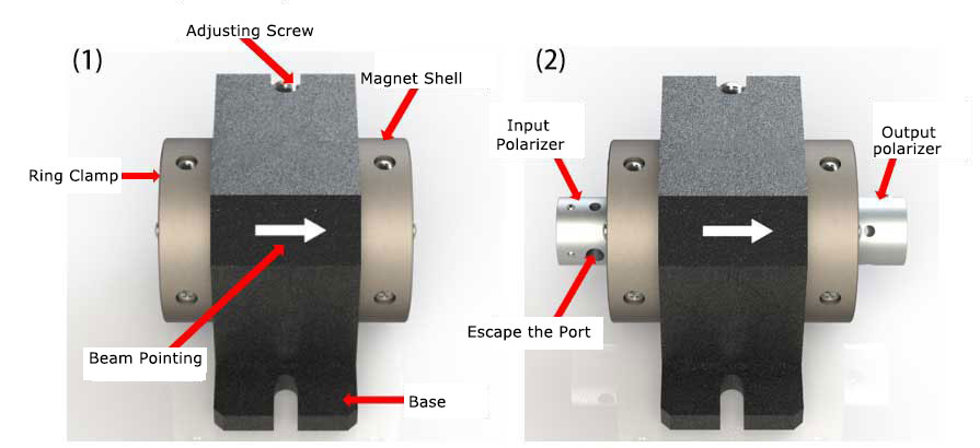
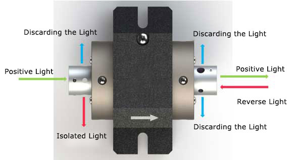
Faraday optical rotator is a kind of magneto-optical device based on Faraday magneto-optical effect, which can rotate the polarization direction of incoming ray polarized light by a certain Angle, and the optical rotation direction is only related to the internal magnetic field, and has nothing to do with the optical direction. Commonly used Faraday optical rotators are designed to rotate at an Angle of 45° or 90°. An optical isolator is formed by placing a 45° optical rotator between two 45° polarized devices. Optical isolator is a kind of unidirectional permeable magneto-optical device, which has been widely used in laser amplification system, mode-locked laser and laser measurement equipment. Figure 1 show the main structure of the optical rotator and the isolator. The isolator is formed by adding input and output polarizers on both sides of the optical rotator.
Crylink offers the CL-ROT series of optical rotator and the CL-ISO series of isolators with wavelengths ranging from 532nm to 1064nm. The through-optical aperture is available in two specifications: 2.5mm and 2.5mm. Different wavelengths and through-optical aperture correspond to different mechanical packaging structures. From small to large, there are three sizes: 1#, 2#, 3#. Our company has professional magneto-optical device design technology and strong OEM production capacity, can provide different optical aperture, wavelength and package size of the non-standard isolator products. We can also supply sub-nanosecond micro laser, semiconductor laser series products, to provide users with complete system design and application services.
Crylink optical rotator and isolator series products have the best performance at the designed wavelength and temperature. When the optometrist or isolator is used out of the designed wavelength and temperature, please contact us for consultation.
2. Product Introduction
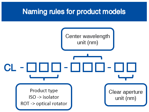
2.1 Product model and naming rule
2.2 CL-ROT series optical rotator product specifications
| Model | CWL | CA | Rotation angle @25℃ | Extinction ratio @25℃ | Transmissivity @25℃ | Damage threshold @10ns | Package type |
| CL-ROT-532-5 | 532nm | 5mm | 45°±1° | >30dB | >95% | 3.5J/cm2 | 2# |
| CL-ROT-633-2.5 | 633nm | 2.5mm | 45°±1° | >30dB | >95% | 3.5J/cm2 | 1# |
| CL-ROT-633-5 | 633nm | 5mm | 45°±1° | >30dB | >95% | 3.5J/cm2 | 2# |
| CL-ROT-780-2.5 | 780nm | 2.5mm | 45°±1° | >30dB | >95% | 3.5J/cm2 | 1# |
| CL-ROT-780-5 | 780nm | 5mm | 45°±1° | >30dB | >95% | 3.5J/cm2 | 2# |
| CL-ROT-785-2.5 | 785nm | 2.5mm | 45°±1° | >30dB | >95% | 3.5J/cm2 | 1# |
| CL-ROT-785-5 | 785nm | 5mm | 45°±1° | >30dB | >95% | 3.5J/cm2 | 2# |
| CL-ROT-1030-2.5 | 1030nm | 2.5mm | 45°±1° | >30dB | >95% | 5J/cm2 | 3# |
| CL-ROT-1030-5 | 1030nm | 5mm | 45°±1° | >30dB | >95% | 5J/cm2 | 3# |
| CL-ROT-1064-2.5 | 1064nm | 2.5mm | 45°±1° | >30dB | >95% | 5J/cm2 | 3# |
| CL-ROT-1064-5 | 1064nm | 5mm | 45°±1° | >30dB | >95% | 5J/cm2 | 3# |
2.3 CL-ISO series isolator product specifications
| Model | CWL | CA | Isolation @25℃ | Transmissivity @25℃ | Polariser | Damage threshold @10ns | Package type | |
| CL-ISO-532-5 | 532nm | 5mm | >30dB | >90% | PBS Cube | 3.5J/cm2 | 2# | |
| CL-ISO-633-2.5 | 633nm | 2.5mm | >30dB | >90% | PBS Cube | 3.5J/cm2 | 1# | |
| CL-ISO-633-5 | 633nm | 5mm | >30dB | >90% | PBS Cube | 3.5J/cm2 | 2# | |
| CL-ISO-780-2.5 | 780nm | 2.5mm | >30dB | >90% | PBS Cube | 3.5J/cm2 | 1# | |
| CL-ISO-780-5 | 780nm | 5mm | >30dB | >90% | PBS Cube | 3.5J/cm2 | 2# | |
| CL-ISO-785-2.5 | 785nm | 2.5mm | >30dB | >90% | PBS Cube | 3.5J/cm2 | 1# | |
| CL-ISO-785-5 | 785nm | 5mm | >30dB | >90% | PBS Cube | 3.5J/cm2 | 2# | |
| CL- ISO-1030-2.5 | 1030nm | 2.5mm | >30dB | >90% | PBS Cube | 5J/cm2 | 3# | |
| CL-ISO-1030-5 | 1030nm | 5mm | >30dB | >90% | PBS Cube | 5J/cm2 | 3# | |
| CL-ISO-1064-2.5 | 1064nm | 2.5mm | >30dB | >90% | PBS Cube | 5J/cm2 | 3# | |
| CL-ISO-1064-5 | 1064nm | 5mm | >30dB | >90% | PBS Cube | 5J/cm2 | 3# |
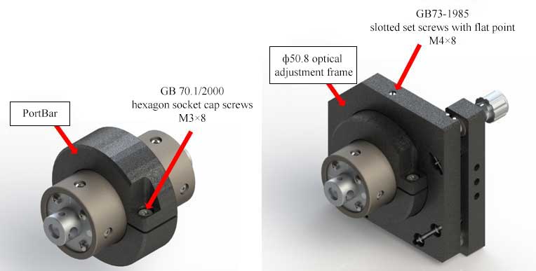
2.4 Machine dimension (mm)
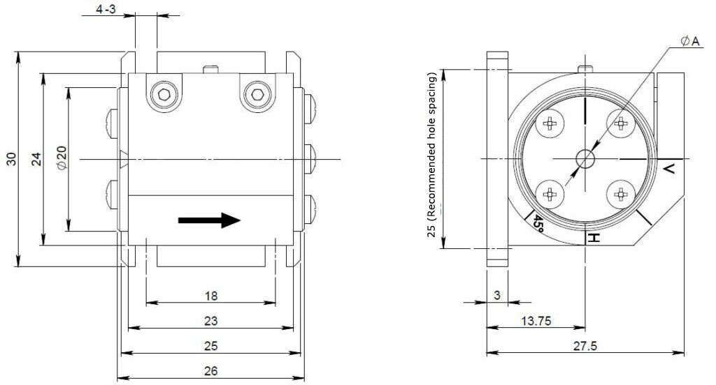
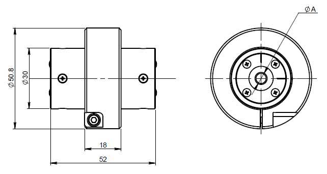
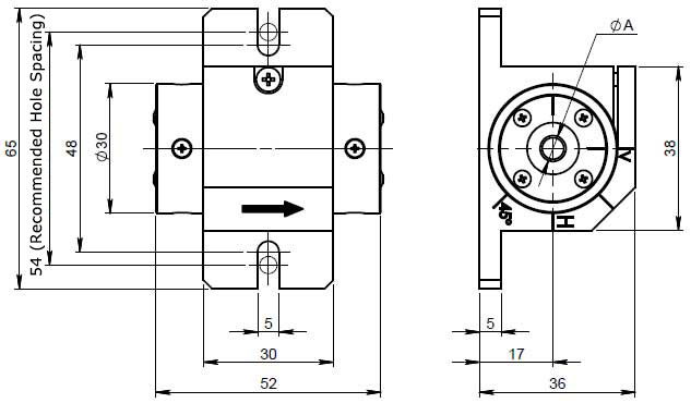
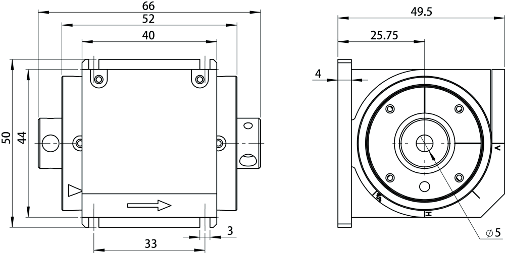
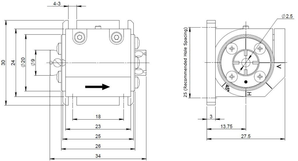
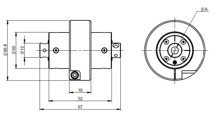
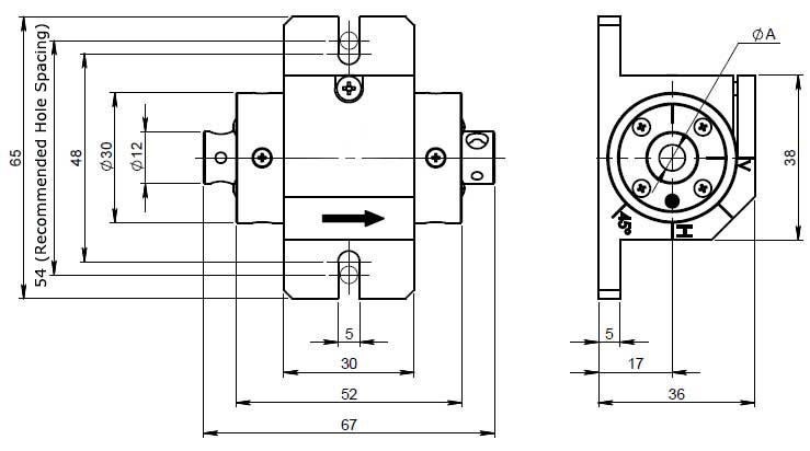
- фA is the optical aperture;
- 1#, 3# package optical rotator /isolator standard configuration of fixed base. 2# package optical rotator /isolator standard configuration adapter, adapter can realize the 2# package and standard (50.8mm optical adjustment frame compatibility, 2# package fixed base is optional, our company can also provide (50.8mm optical adjustment frame standard products.
3. Operation Instructions to the Product
3.1 Safety in use
Warning: Because the product has a strong magnetic field and laser operation is involved in the application, to ensure the safety during use, please read the safety precautions carefully and operate in accordance with the specifications. Otherwise, the product may be permanently damaged or serious injury may be caused to the user。
Attention:
- Don’t use or place ferromagnetic tools or objects near the product. They will be strongly absorbed by the magnetic field, causing damage or injury to human body.
- When moving the product, take it from the side, do not take it from the two ends (that is, from the light hole), because the magnetic field at both ends is the strongest attraction.
- Don’t disassemble the product, as internal magnets may eject and cause serious injury.
- Persons using any magnetically sensitive implant, such as a pacemaker, should consult their physician about any potential complications that may arise from the external magnetic field of the product.
- All magnetically sensitive materials and devices such as watches, mobile phones, computer hard drives and magnetic strips need to be kept away from the product.
- Isolators In typical applications, the reverse isolation of light will exit from an escape port on the side wall of the input polarizer (marked with dots). The user should place an optical trap in the exit direction to terminate the laser and always wear laser safety glasses.
- There are two escape ports each on the side walls of the input and output polarizers of the isolator. If the isolator is incorrectly aligned with the light source or the reverse light has been depolarized, there may be a large amount of reflected light at all ports. It is the user’s responsibility to analyze the specific application and properly manage the light coming from all ports on the product. When possible, keep the strongest reflected light at the level of the workbench or in the safest other direction (usually down into the workbench).
- Never look directly into the product aperture to align the light source or other optical components.
- The user should confirm in advance whether the energy density of the laser exceeds the anti-damage threshold of the product, so as to avoid the damage of optical components caused by exceeding the damage threshold.
3.2 Instructions for use of optical rotators
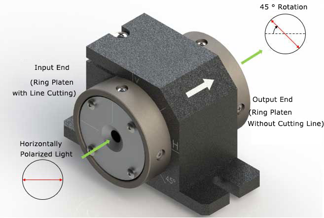
At the designed wavelength and temperature, linearly polarized light is incident on the optical rotator from the input end, and the polarization direction of the output light will rotate 45° relative to the input light. The rotation direction is shown in Fig. 2, where horizontally polarized light is taken as an example. The optical rotation direction is only related to the magnetic field inside the optical rotator, and is independent of the light propagation direction, that is, it has non-reciprocity.
3.3 Instructions for use of isolators
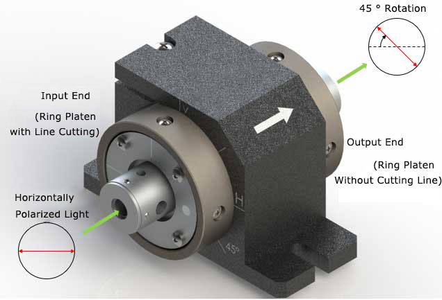
The isolator has the best transmittance and isolation at the designed wavelength and temperature. In a typical application, linearly polarized light from the input to the output (forward light) will pass with minimal loss, while the reverse light will be isolated and the isolated light will exit from the escape port, as shown in Figure 4. The rotation direction of polarization of linearly polarized light after passing through the isolator is shown in Fig. 3.
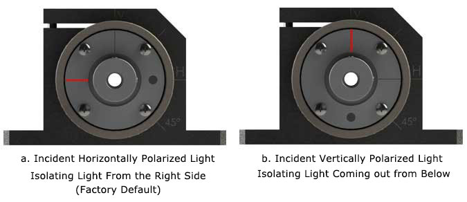
Isolator need according to the polarization direction of the incident light in front of the application of input polarizer calibration, we produce the isolator have been carried out for calibration, when the factory default configuration for the level of polarized light, the ring clamp and the base of the scribed line on the way as shown in figure 5.a, as is shown in red line mark through partial direction of the polarizer, dot mark isolation emergent direction of the light, Now the isolation light is coming out from the right side. Figure 5.b shows the alignment of vertically polarized light, in which isolated light exits from below.
3.4 Resistor Installation
The user needs to carefully align the optical rotators or isolator to the beam path to ensure optimal performance. During alignment, the light source should be operated at a low power to avoid damage to the light source and isolator.
After beam alignment, install the product using the positioning hole provided by the isolator base. Note that the steel wrench will be attracted to the magnetic field outside the isolator. Use two hands, one holding the tool and the other directing the tool where it is going. If possible, use anti-magnetic stainless steel or titanium tools.
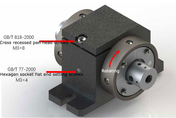
The isolator must be calibrated according to the polarization direction of the incident light before application, that is, to ensure that the polarization direction of the incident light is parallel to the through-polarization direction of the input polarizer. The optical rotator does not require such calibration. Isolator factory default on the level of polarized light, when the incident light is a level of polarized light, the user needs to self calibration, using a wrench to loosen the isolation bottom of the top and side set screw, as shown in figure 6, the rotation of the isolator magnet enclosure, until the output optical power reached maximum, lock screw again, calibration is completed. The engraved lines on the isolator base indicate the vertical (V), horizontal (H) and plus or minus 45° directions. If the polarization direction of the incident light is known, the through-polarization direction of the input polarizer (red line) can be simply aligned with the polarization direction of the incident light with the help of these engraved lines, but the calibration accuracy of this method is not high. During the process of rotating the enclosure of the magnet, the reflected light will exit from the escape port on the side wall of the input polarizer. Precautions must be taken for safety protection. We can also provide pre-calibration service for specified polarization direction, users can contact sales consultation.
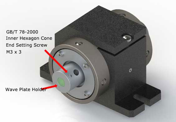
Our company can provide pre-calibration service of wave plate, and users can also adjust by themselves. Use a wrench to loosen the set screws in Fig. 7 (there are two in the symmetric direction), rotate the wave plate seat until the desired output polarization is obtained, and then re-lock the screws to complete the adjustment.
2 # Package optical rotator/isolator optical device (VIS-NIR series in the light of 5mm products) can be used in addition a kind of flexible installation, they can through the adapter with a standard (ф50.8 compatible optical adjustment, as shown in figure 8, the diagram (ф50.8 optical adjustment for our standard product inventory, connecting seat can be adjusted through the set screws in the rack. Different from other packages, the standard configuration of the 2# package is the adapter seat, and the fixed base can be optional.
4. Copyright Notic
The trademarks and names of the software and hardware products mentioned in this manual belong to the corresponding companies.
The copyright of this manual belongs to Nanjing Crylink Photoelectric Technology Co., LTD. No organization or individual may reproduce or disseminate the contents of this Manual by any means or form without the official permission of the Company.
The contents of this manual are subject to change without prior notice.

Frank
Frank graduated from the University of Shanghai for Science and Technology, majoring in optics. As a technical engineer at Crylink Company, he deeply understands crystal materials and laser components.
Related Video(s) with this Article
Related Product(s) with this Article

Related Application(s) with this Article